Point Cloud
This document explains how to view point cloud data in the viewport.
A Point Cloud is 3D point data acquired from 3D scanners or LiDAR.
It records the shape of building interiors and exteriors with precision and is used as reference material when drawing shapes based on real spaces.
Finding Point Cloud Data
In AMapper For ARC eye, point cloud data is already loaded for each Location. You can view it immediately without any additional setup.
You can find point cloud items in the provided Reference Stage.
- Find the Reference Stage in the left Hierarchy Panel.
- Check the PointCloud underneath.
- Toggle visibility with the Visibility Toggle icon.
Checking Point Cloud Information
You can check the current point cloud status in the bottom status bar.
| Item | Description |
|---|---|
| Depth | Current depth level limit applied |
| Points | Number of points currently being rendered |
| Nodes | Loaded nodes / Marked nodes |
Detailed View (Increasing Depth Level)
Point clouds are displayed at a low depth level by default (default: 2).
| Shortcut | Description |
|---|---|
| Z | Increase depth level limit by 1 (max 8) |
- Increasing the depth level loads more detailed points, allowing you to see finer shapes.
- When moving or zooming the viewport, it automatically switches to a lower depth level.
Point cloud data consists of millions to hundreds of millions of points. Rendering all points simultaneously would cause:
- Performance degradation - GPU memory and rendering performance would be strained.
- Network load - Loading large amounts of data takes time.
Therefore, press Z only when needed for detailed viewing, and the system automatically switches to a simplified view during viewport operations.
Adjusting Point Cloud Properties
Select the PointCloud to adjust various display options in the right Properties Panel.
Adjusting settings to match your work environment enables more accurate reference when drawing shapes.
Transform
Configure the point cloud's coordinate system.
| Property | Description |
|---|---|
| Coordinate System | Specify the coordinate system of the point cloud data. |
Coordinate System
AMapper's default coordinate system is Right-handed, Y-Up. If the point cloud data's original coordinate system differs, you can select the correct coordinate system to convert it.
| Coordinate System Example | Description |
|---|---|
| Left-handed, Y-Up | Unity coordinate system |
| Left-handed, Z-Up | Unreal Engine coordinate system |
| Right-handed, Y-Up | AMapper default, Maya, Houdini coordinate system |
| Right-handed, Z-Up | 3DS Max, Blender, AutoCAD, SketchUp coordinate system |
In AMapper For ARC eye, the point cloud coordinate system is already aligned at conversion time, so no adjustment is needed.
However, if the point cloud appears flipped or rotated, the original data's coordinate system may be different, so check this setting.
Material
Configure the visual representation of the point cloud. You can choose from three modes: Standard, EDL, and Custom.
Each mode maintains its settings independently. Changes made in Custom mode are not applied when switching to Standard mode, and vice versa.
Standard Mode
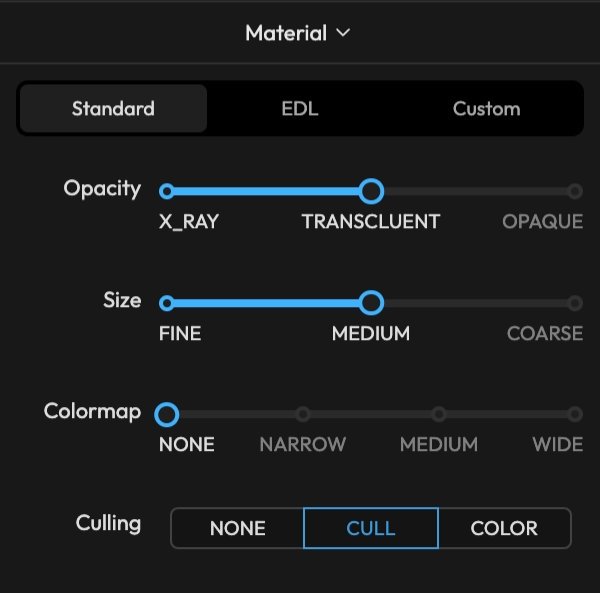
A template mode for quickly applying best-practice combinations using sliders.
| Option | Value | Description |
|---|---|---|
| Opacity | X-Ray | Points appear nearly transparent. Useful when the point cloud should not interfere with shape drawing. |
| Translucent | Displayed semi-transparently. | |
| Opaque | Fully opaque. Depth Test / Depth Write are automatically enabled. | |
| Size | Fine | Displays with a small point size. |
| Medium | Displays with a medium point size. | |
| Coarse | Displays with a large point size. | |
| Colormap | None | Displays in a single color. |
| Narrow | Represents ±25m elevation range from world origin as color. | |
| Medium | Represents ±50m elevation range from world origin as color. | |
| Wide | Represents ±100m elevation range from world origin as color. | |
| Culling | None | Stage ROI culling is not applied. |
| Cull | Hides points outside the Stage ROI. | |
| Color | Displays points outside the Stage ROI in a separate color. |
In Standard mode, Size always operates with Adaptive Size enabled. Point size is automatically adjusted inversely proportional to the camera distance — larger when close, smaller when far.
Applies rainbow coloring based on point elevation (Y coordinate). The elevation range is relative to the world origin (Y=0), and points outside the range are clamped to the end color. Useful for distinguishing floors by color when a building spans multiple stories.
Culling is only effective when a Stage ROI (OBB) is configured. Without a Stage ROI, all points are displayed regardless of the Culling setting.
EDL Mode
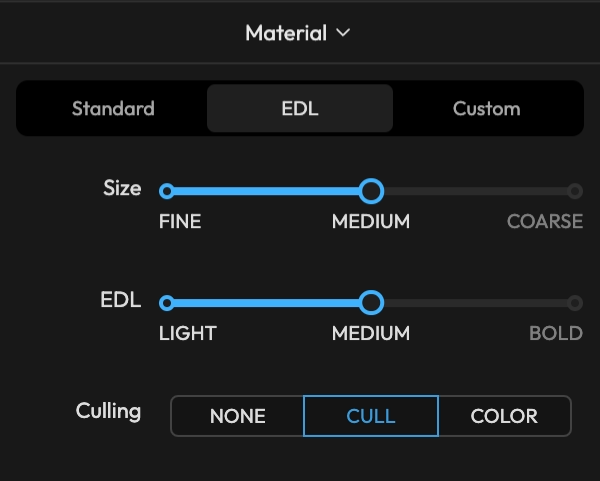
A mode utilizing EDL (Eye Dome Lighting). By detecting depth differences between adjacent points and darkening boundaries, the 3D shape and outline of the point cloud become more distinct. Always renders with opacity 1.0, Depth Test/Write enabled.
| Option | Value | Description |
|---|---|---|
| Size | Fine / Medium / Coarse | Same as Standard mode |
| EDL | Light | Subtle depth emphasis |
| Medium | Medium intensity depth emphasis | |
| Bold | Strong outline emphasis | |
| Culling | None / Cull / Color | Same as Standard mode |
Custom Mode
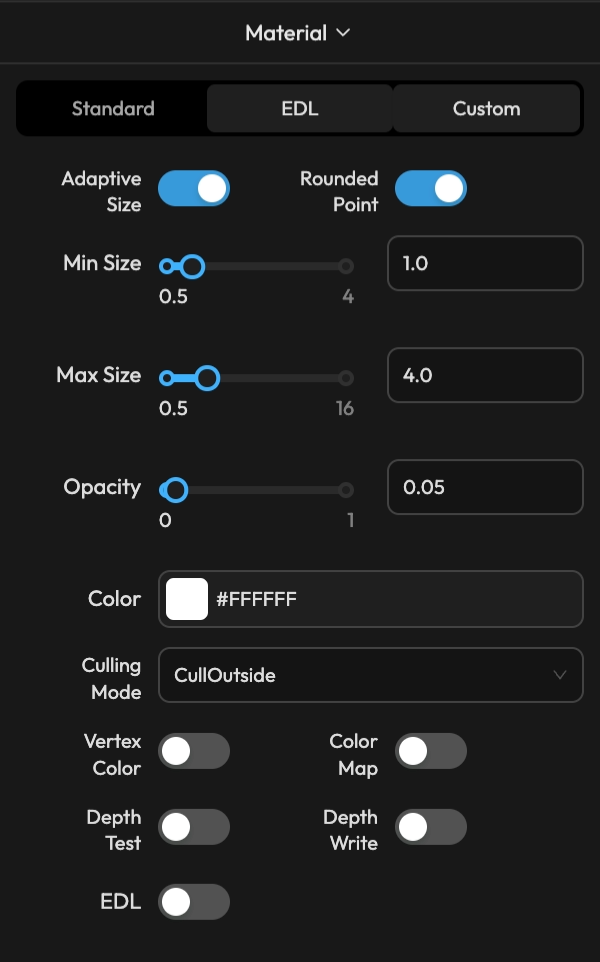
A mode where all parameters can be adjusted directly.
| Option | Description |
|---|---|
| Adaptive Size | ON: Point size is automatically adjusted inversely proportional to camera distance, within the Min Size ~ Max Size range. OFF: Uses a fixed size. |
| Rounded Point | ON: Points are rendered as circles. OFF: Points are rendered as squares. |
| Size | Fixed point size when Adaptive Size is OFF. |
| Min Size | Minimum point size when Adaptive Size is ON. |
| Max Size | Maximum point size when Adaptive Size is ON. |
| Opacity | Sets point opacity. |
| Color | Displays in a single color when both Vertex Color and Color Map are OFF. |
| Culling Mode | Disabled: No culling / CullOutside: Hide points outside Stage ROI / ColorOutside: Display points outside Stage ROI in a specified color |
| Culling Color | Color for points outside the OBB when Culling Mode is ColorOutside. |
| Vertex Color | ON: Uses original data colors. OFF: Uses the Color setting. |
| Color Map | ON: Applies gradient coloring based on point elevation (Y coordinate, relative to world origin). |
| Depth Test | ON: Points are occluded by objects in front. OFF: Points are always visible (X-Ray effect). |
| Depth Write | ON: Points are written to the depth buffer, occluding objects behind them. |
| EDL | Enables Eye Dome Lighting. |
| EDL Radius | Influence radius of the EDL effect. Larger values emphasize outlines over a wider range. (when EDL is ON) |
| EDL Strength | Intensity of the EDL effect. Larger values produce darker boundary emphasis. (when EDL is ON) |
Layer Type Toggle
Quickly toggle point cloud layer visibility using the toggle button on the right side of the status bar.
| Shortcut | Description |
|---|---|
| 1 | Point Cloud Layer Visibility (1) toggle |